Railway Modelling
Modelling 2 HAP units
(4mm scale)
|
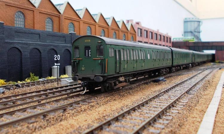
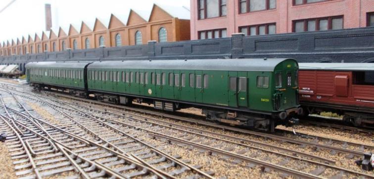
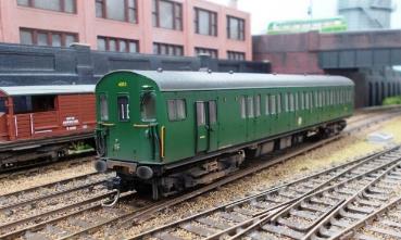
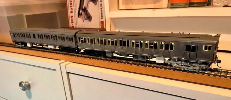
Bachmann 2 HAP no.6008 (Phase 1 /Batch 1 conversion) thence weathered
by TMC. |
2 HAP units
Most
Southern Region modellers will be aware of Bachmann excellent 2 HAP model, unit
no.6061 in original green livery. This unit was a 1958-built Phase 1 /Batch 2
unit with 1957 control equipment, no roof-mounted lighting conduits
and other detail differences such as stepboards. This
model also correctly features the original larger-style of headcode numerals
which did not include red blinds; initially a tail-lamp was carried.
By using
other Bachmann components, the dedicated modeller can create an earlier 1957-built
Phase 1 /Batch 1 unit which had 1951 control equipment, roof-mounted lighting
conduit and so forth.
Except the later
Phase 2 units (1961-built Batch 3 & 1963-built Batch 4) were visually very
different starting with the use of external quarterlight frames, large opaque lavatory
sidelights (windows), differing roof gutters and in the case of Batch 4 units,
different cab fronts with a smaller headcode box.
The DC kits
2 HAP kit forms an excellent basis for producing these Phase 2 units and
retired Motorman Dave Deadman (of the South Eastern Engineman’s Model Railway
Club) provides a detailed description on producing
a model of the last 2 HAP (Phase 1 /Batch 4) unit no.6173.
All these
detail differences can be found in the BR(S) 2 HAP history.
|
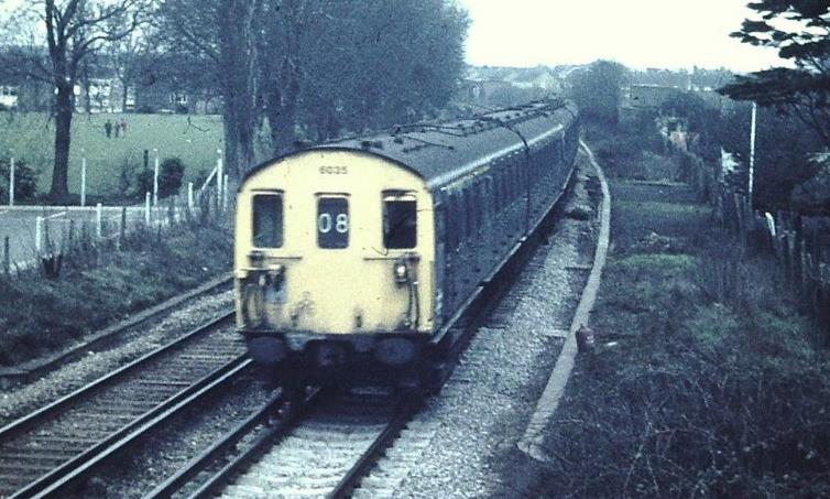
2 HAP unit no.6035 (Phase 1 /Batch 1) near Rainham © BlooandCustard |
Modelling a Phase 1 /Batch 1 Unit
Overview
The first batch of forty-two units (nos.6001 – 6042) were
‘1951 type’ stock with similar electrical equipment to the 1951 built
4 EPB units and BR 2 EPB units with contactor control.
Visually the ‘1951 type’ Phase 1 units had roof-mounted lighting conduit
including the piping to the lavatory water tanks. The jumper cable boxes
between units were of the ‘1951-type’ as was the underframe equipment. The stepboards ran full-length of the underframe. In later
years the stepboards gained a break underneath the opaque
toilet sidelight and between the last two seating bays on the driver’s side
when speedometers were fitted.
On all of the Phase 1 units (first and second
batches) the passenger quarterlights were fitted from inside the car and sealed
with mastic, so they were almost flush with the bodyside.
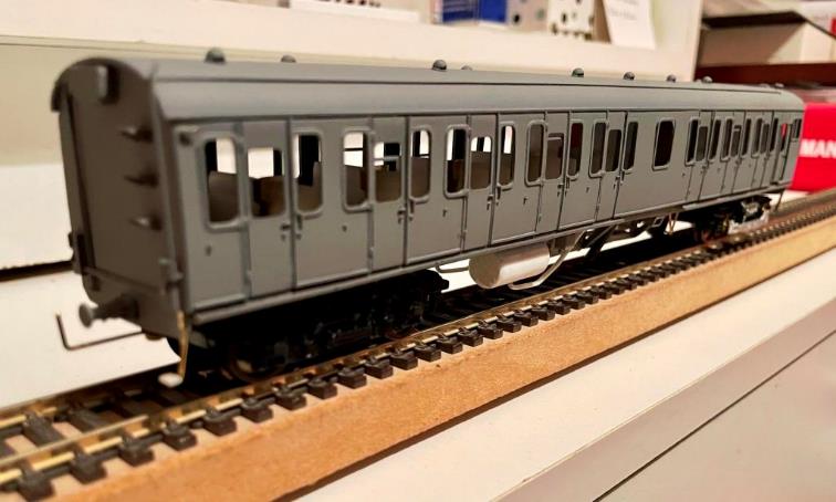
Modelling
This is a relatively straightforward conversion from
the Bachmann Phase 1 /Batch 2 model, so a lengthy
explanation is probably not necessary. Essentially alongside a Bachmann 2 HAP
unit, one of their 2 EPB units is also required and (to make life even easier)
the roof from a Kernow 2H DTC – preferably utilising either 2H ‘Hastings’ unit
nos.1121 or 1122 which should not have been modelled with the roof-mounted
lighting conduit.
Essentially
the 2 HAP coach bodies (DTC & MBSO) are refitted onto the 2 EPB underframes
to give the correct stepboards and 1951-type control
gear. The roofs of the 2 HAP MBSO and 2 EPB MBSO are swapped over, as are those
of the 2 HAP DTC and 2H DTC to give lighting conduit along the 2 HAP unit.
To be
really accurate the roof-top end jumper boxes should also be changed but this
entails much additional detailing work on the inner ends of the coaches and in
terms of this conversion modellers will need to take their own view relative to
the additional work involved.
Besides the
2H (whose motorcoach roof would need altering with a sharp blade) the modeller
is left with a spare 4 EPB motorcoach and a 2 EPB driving trailer on a later
underframe (possible starting point for a 3T centre-car conversion perhaps?)
|
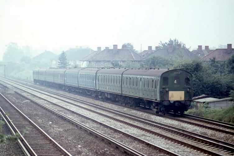
Leading an 8 HAP
formation along the Up Fast through Petts Wood on Sunday, 27th
August 1967 is ‘Kent Coast’ Phase 1 ‘Second batch’ unit no.6094;
headcode ‘4’ being a Margate to Charing Cross via Dover service. Shewing signs of
acid-wash, no.6094 is the only unit in the formation not equipped with UIC 1st
class cantrail banding; it probably did not receive this (or a air-horns) until repainting in
blue livery at Eastleigh Works in April 1969. Second unit is a
SR-type 2 HAP and (with its roof-mounted lighting conduits and continuous stepboards) 3rd unit is ‘1951’-type Phase 1 ‘1st batch’. Sporting
high-level rainstrips the last unit in the train is
clearly a 1963-built Phase 2 ‘4th batch’ unit. © Robert Carroll |
Modelling a Phase 1 /Batch 2 Unit
Overview
The second batch of units (nos.6043 – 6105) were ‘1957 type’
stock and visually these Phase 1 units did not have any roof-mounted lighting
conduit but did retain the piping to the lavatory water tanks. The jumper cable
boxes between units were of the ‘1957-type’ as was the underframe equipment.
The stepboards gained breaks underneath the opaque toilet
sidelights and between the last two seating bays on the driver’s side when
speedometers were fitted.
On all of the Phase 1 units (first and second batches) the passenger quarter
lights were fitted from inside the car and sealed with mastic
so they were almost flush with the bodyside.
Modelling DC Kits
The DC Kits was an excellent basis for a 2 HAP and
is disappointing that these are no longer produced. /unit no.6066 was built by
Dave Deadman for career railwayman, (the late) Derek Janes who chose
no.6066 because he had driven a special with the 12”=1’
prototype unit back in the 1960’s when this unit was experimentally fitted with
AWS equipment.
Some construction
details differ from the Phase 2 /Batch 4 unit no.6173
such as the use of the DC kits plastic bogies instead of replacement with MJT
cast bogies.
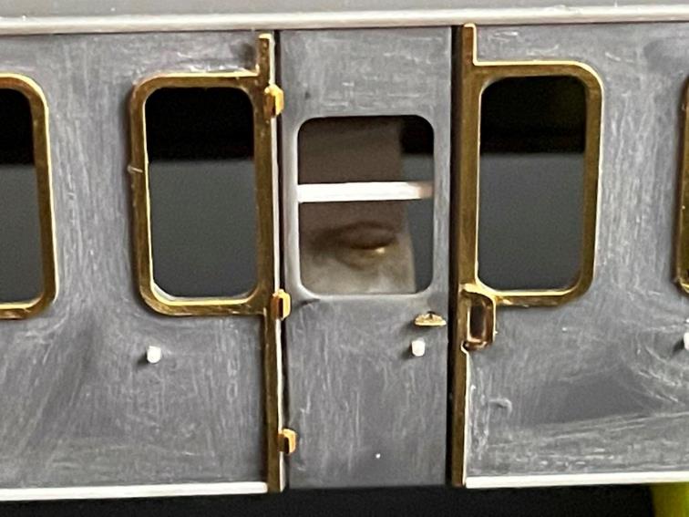
|
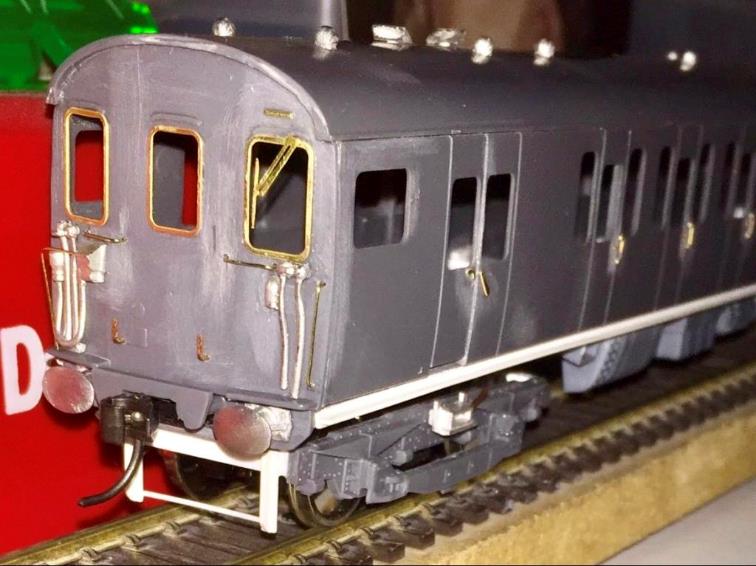
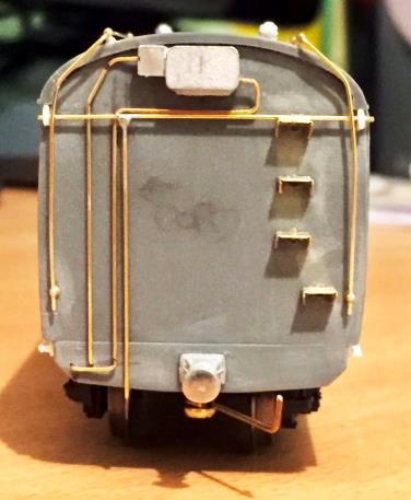
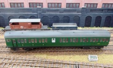
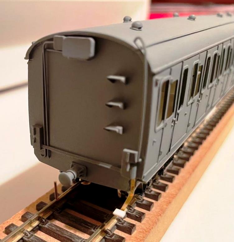
Motorcoach cab-end detail |
|
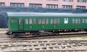
Driving Trailer Composite |
|
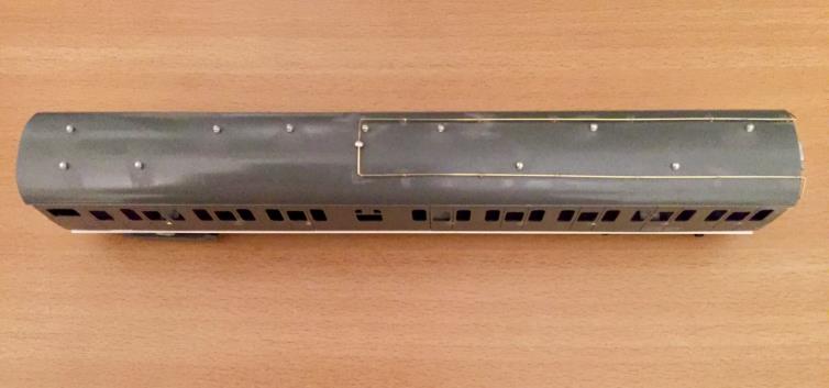
Driving Trailer Composite roof detail |
|
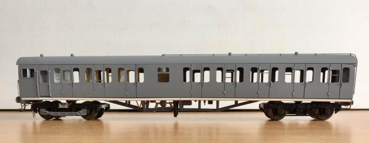
Motorcoach secondman’s side |
|
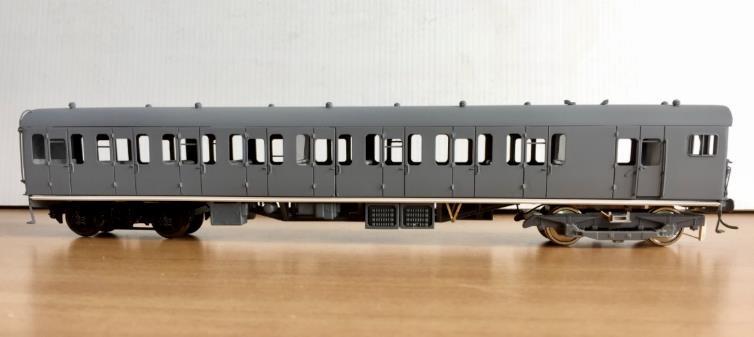
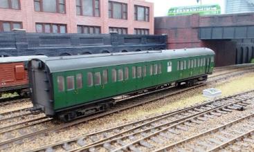
Driving Trailer Composite driver’s side |
Modelling Bachmann
Bachmann produce a Phase 1 /Batch 2 unit so there
probably little else to add in respect of their excellent Batch 2 models.
|
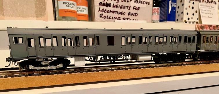
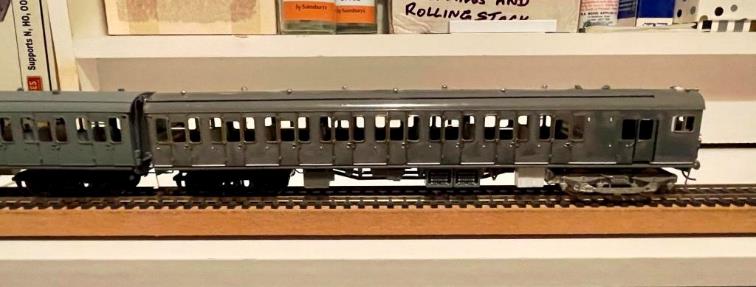
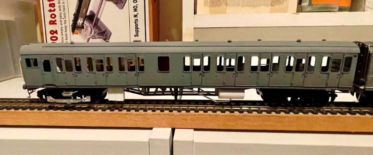
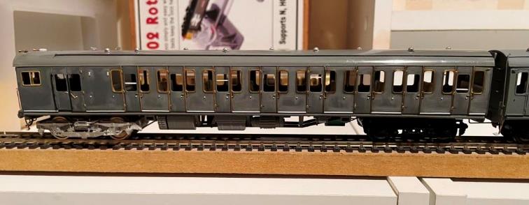
Bachmann 2 HAP (Phase 1 /Batch 2) renumbered to 6053 & weathered
by TMC. |
|
|
|
|
Distressed DTC |
Darkened & distressed roof |
|
|
|
|
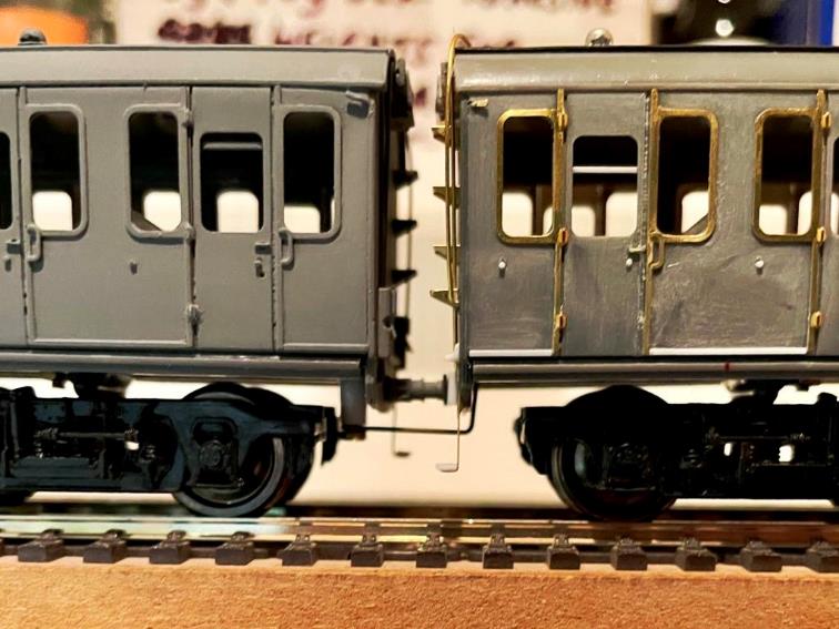
Note how the carriage washing machine brushes only reached partway between the inner ends. |
Distressed MBS |
|
The term weathered isn’t entirely
correct for units attract much dirt and grime (along with wear & tear)
leaving them in a distressed condition. In terms of distressing Southern
Electric units of the late fifties /early sixties, TMC really have got this down to a fine
art!
|
|

However, what is worth stating the Bachmann 2
HAP comes with two lengths of fixed coupling bar for use within the set. The
shorter bar lets the DTC’s centre buffer touch the MBS’s rubbing plate and
really looks the part. Except when several 2 HAP units are running in multiple
the intermediate couplings can compress leading to the roof-mounted jumper
boxes making contact on curves.
|
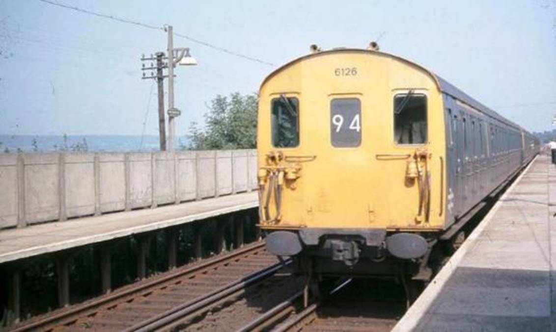
2 HAP number 6126 (third batch
‘1961’ Phase 2) entering East Malling |
Modelling a Phase 2 /Batch 3 Unit
Overview
The third batch of forty-one units (nos.6106 – 6146) were
outshopped in 1961 and were ‘1957 type’ Phase 2 units with may
differences from the two earlier Phase 1 batches.
Visually the 1961 build of Phase 2 units did not have external roof
conduit. The jumper cable boxes between units were of the ‘1957-type’ as was
the underframe equipment. For all of the batch there
was a break in the stepboards where the toilet
compartment was located.
However, during production the designed changed from a continuous gutter
to individual gutters above each doorway. This change occurred after unit
no.6126 (outshopped 6th July 1961) but before unit no.6141
(outshopped 25th November 1961); information to the exact unit
change is sought and sadly Eastleigh’s Works Records do not provide a clue as
to the 2 HAP unit changeover point.
On all of the Phase 2 units (third and fourth batches) the
passenger quarterlights were fitted with a rubber gasket resulting in an
external sidelight frame. They also had one-piece opaque lavatory sidelights
without sliding ventilators. Phase 2 units were also equipped with Commonwealth
bogies at the inner end of each car.
Modelling
These units can be made from the DC kits using
a similar method and components as the Batch 4 units (see below).
|
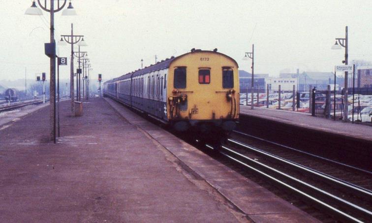
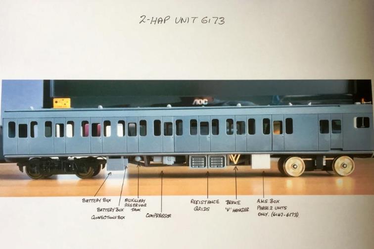
Unit no.6173
– the last slam-door electric unit to be built as Eastleigh. Upon entering
service this unit (along with others) was initially based at Streatham
Hill for use on night trains to Gatwick Airport. Its final day in traffic was 1st October 1984. © BloodandCustard |
Modelling a Phase 2 /Batch 4 Unit
Overview
The fourth batch of twenty-seven units (nos.6147 – 6173) were outshopped
in 1963 and were ‘1957 type’ Phase 2 units with detail differences
from the earlier batches.
Visually the 1963-build of Phase 2 units did not have external roof
conduit. All were built with individual gutters for each door. However, they
were additionally equipped with roof-mounted rainstrips.
These Batch 4 units also featured a modified cab end arrangement with a
smaller headcode aperture and slightly tapered windscreens. The jumper cable
boxes between units were of the ‘1957-type’ as was the underframe equipment.
The stepboards ran full-length of the underframe.
On all of the Phase 2 units (third and fourth
batches) the passenger quarterlights were fitted with a rubber gasket resulting
in an external quarterlight frame. They also had one-piece opaque lavatory sidelights
without sliding ventilators. Phase 2 units were also equipped with Commonwealth
bogies at the inner end of each car; Batch 4 reverted to the use of BR
Mark 4 motor bogies.
Modelling Unit no.6173
By Motorman Deadman
This
is a description of how I built the DC Kits BR-designed 2 HAP EMU.
Unit no.6173 was chosen because not only it the last 2 HAP
constructed but was also the last slam door EMU built at Eastleigh Carriage
Works. In addition, units no.6172 & 6173 were outshopped with experimental fluorescent lighting
(although this was later removed).
Sadly, the DC kits model is currently unavailable except
occasionally on eBay and even then, commanding high prices nowadays. Plastic
Weld liquid glue was used throughout its construction including gluing the
etched brass to the plastic body.
Commode handles,
hinges, door ‘T’ handles are all by MJT from Dart Castings (reference 2930) as
are the windscreen wipers (reference 1104). The scalloped dome roof ventilators
are MJT reference 2943 with Wizard Models BR periscopes (reference C16).
The door bump-stops
are 0.5mm plastic rod fed into pre drilled holes from the inside of the coach
body. Always remember to clean the surface of these kits to remove the moulding
agent [good old-fashioned Vim powder is excellent for this - ED]. It
will help the liquid glue to bond surfaces together.
|
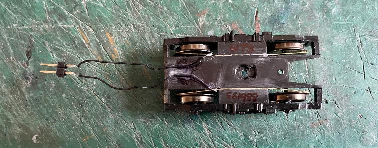
Driver’s side underfloor equipment of a 2 HAP (Batch
4) motorcoach. © Motorman Deadman (1) |
|
Secondman’s side underfloor equipment of a 2 HAP
(Batch 4) motorcoach. © Motorman Deadman (2 |
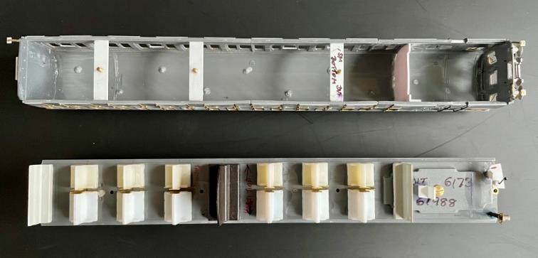
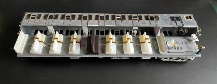
|
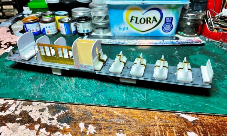
This shows the mainly plastic
construction of the Driving Trailer Composite. The seats are by Southern
Pride Models (reference P.34 [two seats] & P.75 [three seats] high
density seating). The etched seat ends are the ex. Comet Models reference C4
now part of Wizard Models. They also do the seat ends for Bulleid
and Maunsell coaches which is reference C3. First-class
seats are reference P.32 and one had to cut-up to make the four first class
seats behind the Driving cab. Toilet partitions are Plastikard. The cab and brake partitions have
been deliberately left off until the model has been painted as it makes
glazing easier in an otherwise confined space. © Motorman Deadman (3) |
|
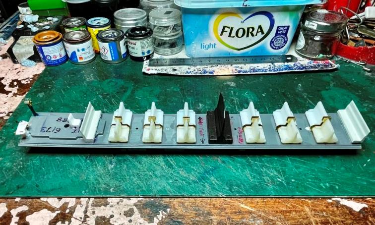
This is the Motor Brake Second
with the same Southern Pride Seats with additional 6-aside suburban seating
at the saloon ends (reference P.37). The odd black seat and partition
is cut from a Replica Railways seating unit freely available from their
website. The guard and driver’s seats are left-overs from previous projects
where Southern Pride seats have been chopped about. © Motorman Deadman (4) |
|
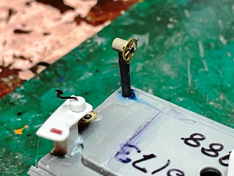
Home-made MBSO driver’s desk and
handbrake with a Roxey Mouldings etched brass
handbrake wheel held in place with a stub end of a Peco
track pin head. The handbrake does revolve around although not connected to
the brake rigging! © Motorman Deadman (5) |
|
Close-up of the Southern Pride
seats and the Wizard Models etched brass seat ends (reference C4). There
isn’t a very wide aisle between the seats as the edge of the floor needed to
clear about 1.5mm each side to allow the plastic sides to clear the seating
thereby reducing the amount of central aisle width. © Motorman Deadman (6) |
|
Overall
view of 2 HAP unit no.6173. © Motorman Deadman (7) |
|
Driving Trailer composite showing
the AWS box (bottom left) scratch built from Plastikard,
one of the two toilet waste pipes and one of two toilet water tanks and
associated piping. All made from a combination of Plastikard
and Plastruct. © Motorman Deadman (8) |
|
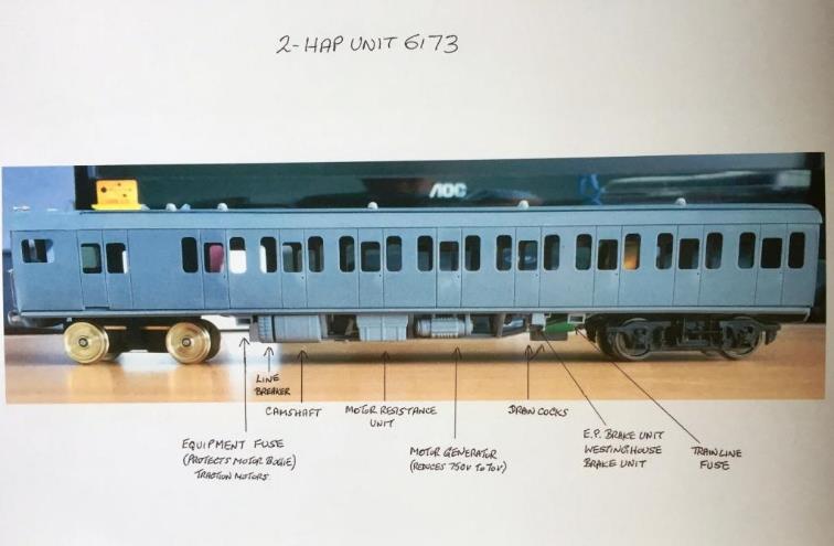
This shows the Motor Brake Second
from the Secondman’s side. The underframe electrical equipment is Southern
Pride Models 2-car/MLV modules kit (reference P.311 or you can buy P.310
which is for a 4-car & doubles up on everything in P.311). These kits have every piece of
equipment for all BR(S) EMU’s and at £8.80 for a 4-car (price correct to
2021), are excellent value. © Motorman Deadman (9) |
|
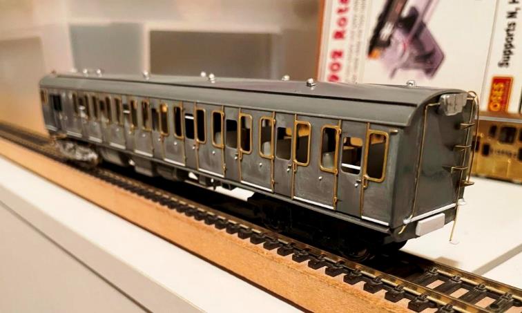
Again, we see the Driving Trailer
Composite from the driver’s side. The etched exterior quarterlight frames and
door strips are from Phoenix Precision Paints under the NNK (No Nonsense
Kits) section (reference 4-40161). They are expensive as each coach will cost
£10.00 to fit out but the overall effect is worth it. © Motorman Deadman (10) |
|
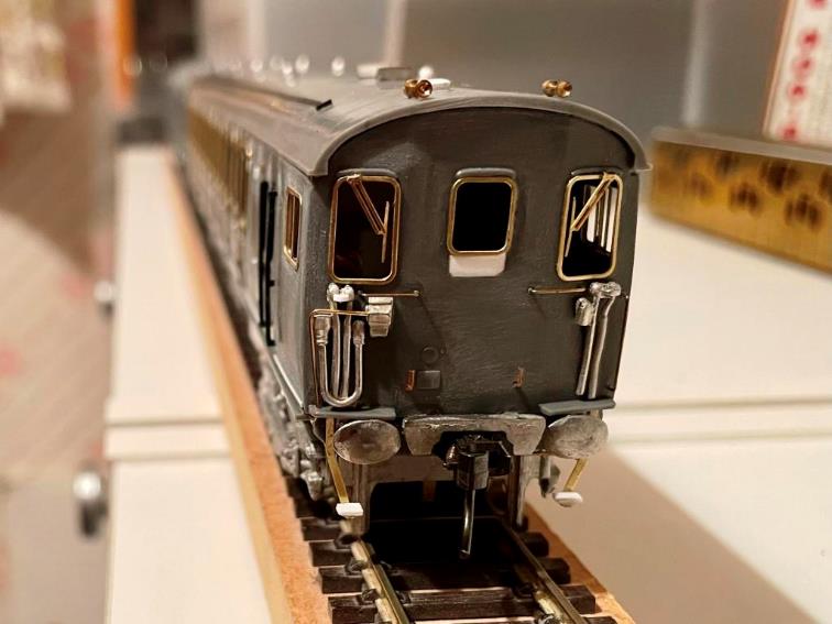
This is the front
end with the headcode panel partly filled in to represent the later smaller
BR(S) headcode used from 1963. The etched brass frames for driver
/secondman’s observation lights (and headcode) are from Phoenix Precision
Paints NNK section (reference 4-40156). The white metal 27-way control jumper
and main reservoir and train pipe castings are by MJT from Dart Castings (reference
1111). The very nice brass
air horns are from Markits. Remember the small air
horn is always on the Driver’s side; large air horn on the Secondman’s side! Handrails are all
home made using 0.45 brass wire including the conduit running down the edge
of the tumblehome (Secondman’s side) coming from the shed jumper box which is
next to the 27-way control jumper. The shed jumper
carries 750 line-volts to the power junction box under the train after being
connected to a shed jumper supply in a depot where there is no live rail and a trolley pole is then attached to it which
provides 750 volts to drive the train out of the shed onto a live conductor
rail at walking pace after which it is removed. The trolley runs along the
length of the shed roof on an overhead track. © Motorman Deadman (11) |
|
This shows the inner end of the
Motor Brake Second with the etched brass steps provided with the kit, plus 0.45
brass wire conduit and various sections of Plastikard
and a central rubbing plate for the centre buffer. The very nice roof jumpers are
produced by Dart Castings (reference unknown) and
they do both motor coach and trailer coach as these are both different. The motor coach has the power
jumper box on the Secondman’s side whereas the trailer coaches have it on the
Driver’s side so that the trailer and motor coach roof jumpers are always a
mirror image of each other. Between two trailer coaches, the
roof jumpers are the wrong way around as it were and
the jumper cables had to be crossed over. © Motorman Deadman (12) |
|
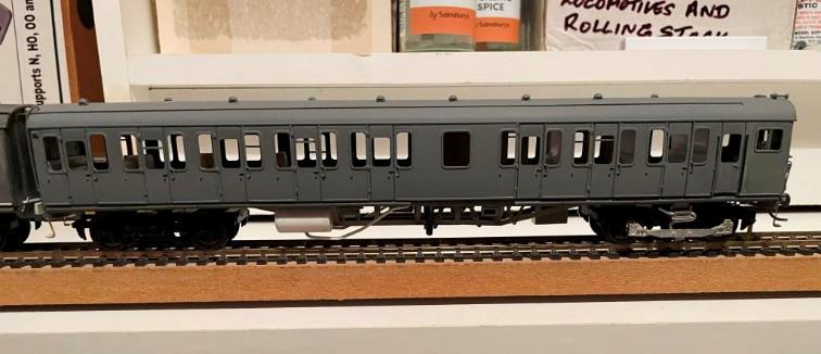
This is the Driving Trailer
Composite seen from the Secondman’s side showing the other toilet waste pipe
and the other toilet water tank and pipe work. Also visible on the solebar to
the right of the (opaque) toilet sidelight is the Train Line Fuse Box. © Motorman Deadman (13) |
|
Driving Trailer Composite inner
end showing home-made lower step from brass waste and a plastic strip for a
step. © Motorman Deadman (14) |
|
Driving Trailer Composite showing
the home-made 0.7mm brass hook and the white metal inner central buffer is
NNK (reference 4-40136). © Motorman Deadman (15) |
|
Driver’s side of the Motor Brake
Second. The Commonwealth bogies are from Bachmann (reference 36-008A) and the
motor bogie is from Black Beetle 35mm wheelbase with 14mm wheels. The white metal motor bogie frames
are from MJT Dart Castings (reference 1105) and the
very nice shoe fuse boxes are from NNK (reference 4-40180). © Motorman Deadman (16) |
|
Close up
of the inner ends, the etched brass quarterlight frames & door furniture. © Motorman Deadman (17) |
|
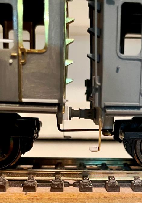
Close-up of the unit coupled
together with a simple hook going underneath the headstock of the Motor Brake
Second which has been screwed to a length of Plastruct
plastic tube and glued to the underside of the Driving Trailer Composite
coach. The centre buffer touching the
rubbing plate can be clearly seen; the rubbing plate was always on the
motor-coach of Southern Electric stock. © Motorman Deadman (18) |
|
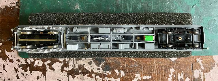
Underneath of the Motor Brake Second showing Southern Pride Equipment
modules. These were from my spares box (with the exception
of a main reservoir tank which was cut off from the end of a round
pencil)! Pencils also make very good vacuum tanks as well. The two bogies are
linked electrically with miniature connectors to give an all-wheel pick up.
The motor coach brake cylinders are available from Phoenix Precision Paints (reference
4-40120). © Motorman Deadman (19) |
|
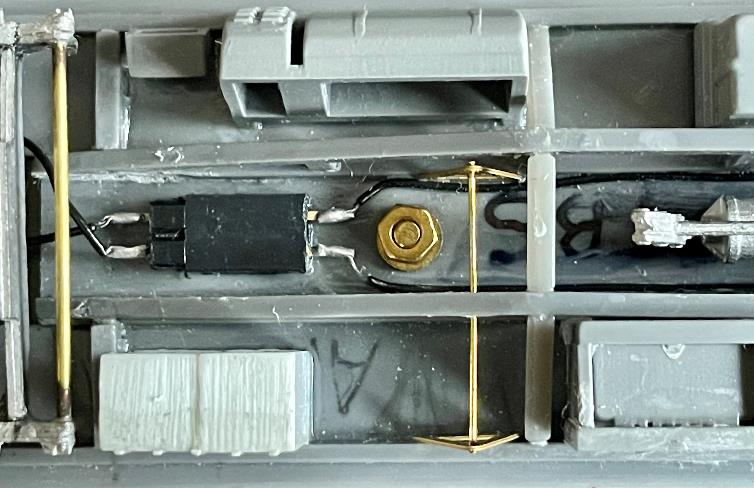
Close up showing one of the mini connectors. © Motorman Deadman (20) |
|
Kadee No. 5 coupling secured with a nut and bolt. © Motorman Deadman (21) |
|
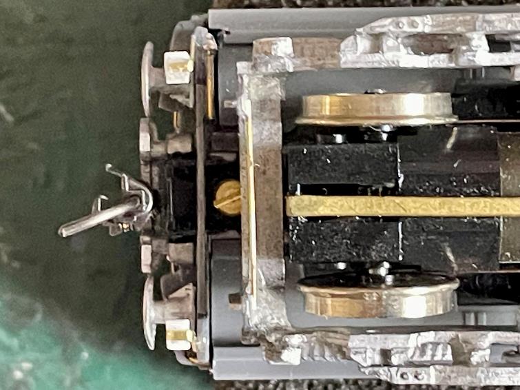
Next the pickups are made - a groove is cut into
each side of the bogie using an Olfa knife. When
the groove is deep enough, two lengths of 0.33 straight brass wire 55mm long
is placed centrally into both grooves and secured with thin superglue along
the length of the grooves and allowed to set. A sanding stick /file /Emery Board is used until the
top of the bogie is totally smooth. Then each pickup is pulled upwards &
bend outward towards the wheel. Afterwards the bent pickup is pushed downwards with
a flat screwdriver until it’s horizontal touching the wheel. Ease it back
gently if it is causing too much resistance. Finally, the pickup wires are
soldered to the male connector. © Motorman Deadman (22) |

|
Underside of the Driving Trailer Composite showing the two toilet
waste pipes and water tanks with their associated pipes. The trailer brake
cylinders are available from Phoenix Precision Paints (reference 4-40137). © Motorman Deadman (23) |
|
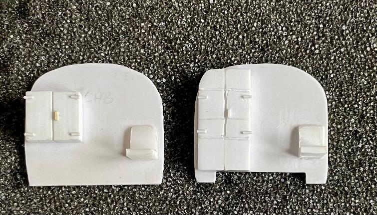
These are the cab bulkheads hand made from Plastikard
and Plastruct. They are painted light green and
added at the very end after painting & glazing is complete. © Motorman Deadman (24) |
|
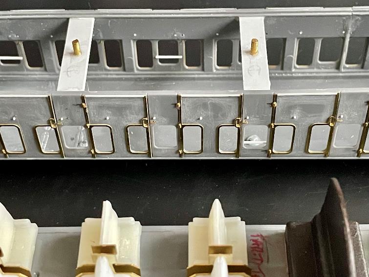
7mm wide /32.5mm long Plastikard strips are
glued inside both edges of the coach, always using the compartment doors as
an anchorage point so that the spacer sits each side of the seats. © Motorman Deadman (25) |
|
Temporarily holding the underframe and body together, drill through
the floor and gently turn the drill until it provides a small indentation on
the underside of the plastic spacer. Do this to all the holes and spacers.
Remove the underframe and put carefully to one side. Take the body, support
the spacer each side with thumb and forefinger and gently drill through each
spacer. © Motorman Deadman (26) |
|
Clean both sides smooth, take a 2mm x12mm
brass bolt, thread it through the inside of the spacer and secure underneath
with a nut and washer making sure the bolt is vertical. Then carefully cover
the head of the nut with superglue and allow to harden. © Motorman Deadman
(27) |
|
Enlarge slightly all the holes in the floor
as it will make it easier to accept the brass bolts when the body and
underframe are joined together. Then unscrew and remove all the washers and
nuts and offer the body to the underframe. © Motorman Deadman (28) |
|
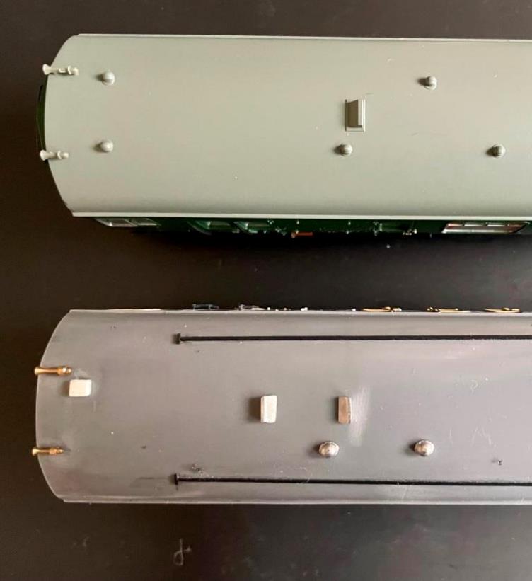
Once your model is complete, it is advised to spray
it with Halfords grey primer to show up any blemishes which is now the time
to rectify them. Final livery colour is your own choice. Once my new ‘paint-shop’ is completed unit no.6173
will be sprayed with Phoenix Precision Paints P.124 B.R. Electric Stock Green
1959-1966 (date should read 1957-1966 although some 4 SUB units received
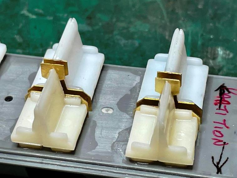
green later even later). Comparison of 4 CEP (top) and 2
HAP (bottom) Motorcoach roofs. © Motorman Deadman (29) |